Guitar Playing Machine From Youtube
Progress Report Week 1
Total Hours:
This week we worked on the first homework, assigned roles, discussed times that we would normally be free and talked a little bit about logistics of the project and some of our ideas. This was more of an introductory week so not as much was accomplished.
Progress Report Week 2
Total Hours: 5
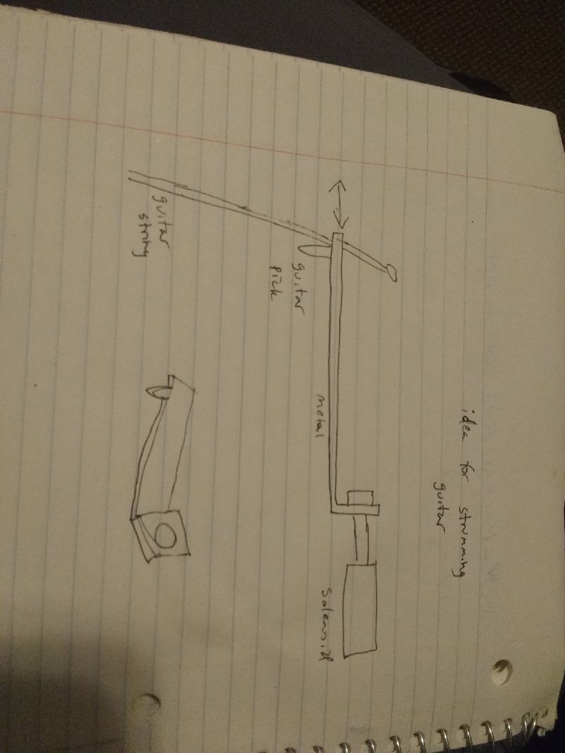
This week, our group tested a variety of different solenoids which would be used to push down on the frets so that the strings could be plucked and have certain notes played. We tested the solenoids at various voltages and through different means to make the pressing down more effective. I made some suggestions such as to hold the guitar on it’s side which worked out pretty well, and to hold it closer, but unfortunately holding it closer actually made it less effective because it wasn’t able to generate the proper speed if held too close. We also came to some realizations such as that the acoustic guitar strings are too close together and that there wouldn’t be enough room on the small fret board for 6 large solenoids to press down on all of them without accidentally hitting another string. Also there was a large gap between the string and the actual fret and one suggestion I made to this that we haven’t tried yet is to put a small piece of wood between the string and the fret board so not as much force will be needed. We’ve considered possibly using a different kind of guitar to solve this issue such as maybe an electric guitar and we were also given a suggestion to use servos instead of solenoids. We looked at various youtube videos and sources trying to come up with a good idea for effectively pushing down on these notes and one video that we came across was an automatic guitar player that used small levers to be able to push down more effectively. I explained to the group that I liked this idea because not only does it solve the force problem, but each lever connected to a thin metal rod to push down on the notes eliminated the space issue. Over the end of this week and next week, we are going to try and finalize our ideas for how mechanically this should work.
Guitar Playing Machine From Youtube
Progress Report Week 3 Total Hours: 6
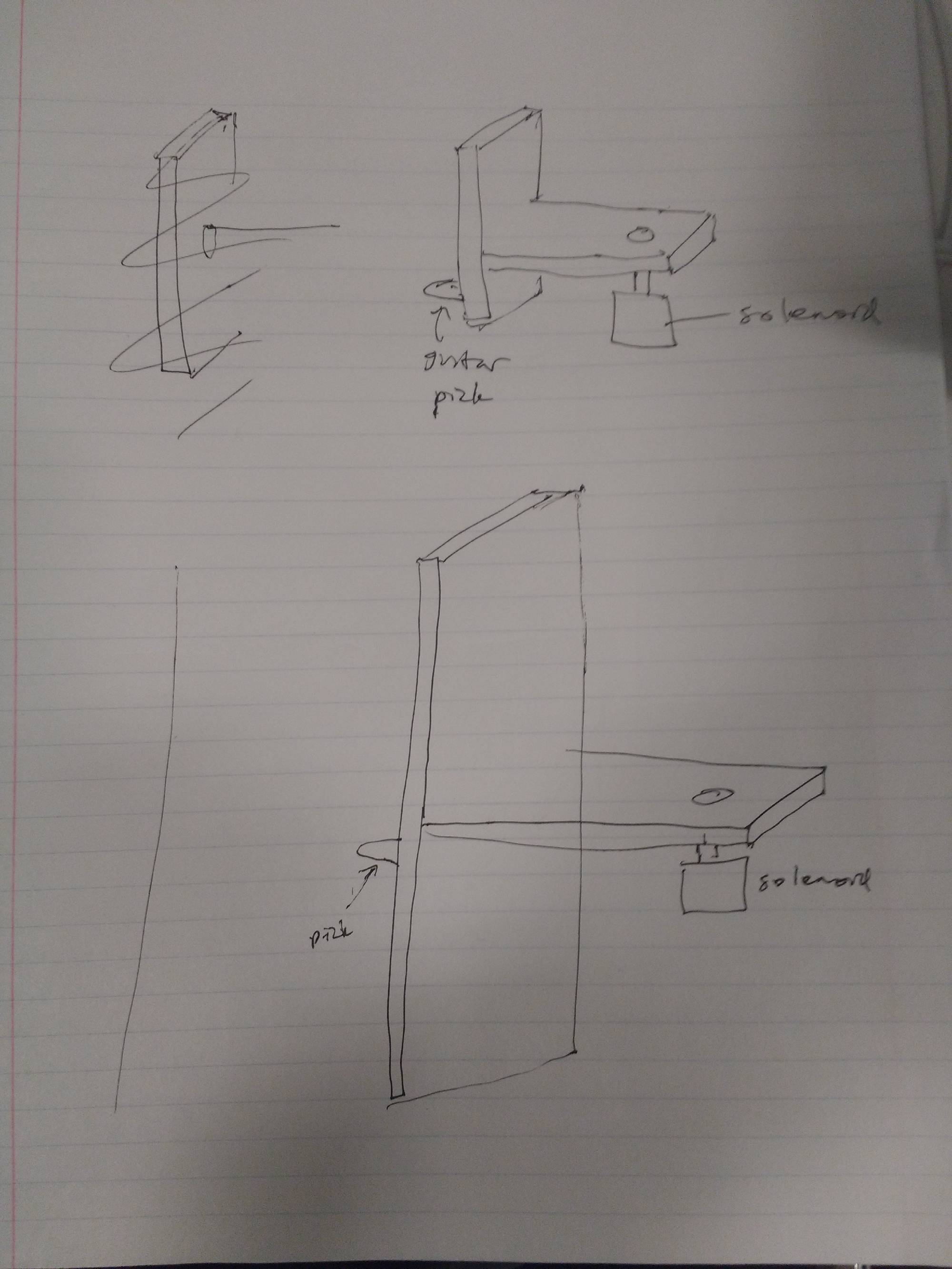
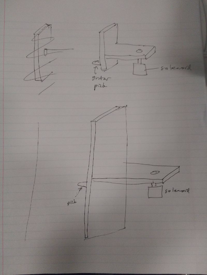
This week, our group worked on designing an effective way to push down on the frets of the guitar and strumming the strings. When we were just directly pushing down with the solenoid, that wasn’t creating enough force so we came up with the idea to create a lever to generate more torque to be able to hold down the note. Wuxicheung designed a prototype in the machine shop and we tested it during man lab. I made some suggestions like keeping the ratio of length on one side to length on the other the same while decreasing the overall length to provide more room. Doing this would also allow for more space between the lever and the string which would be important further down the fret board where more space is needed. I also suggested to fill in empty crevasses with hot glue to keep it more stable. Wuxicheung made the appropriate changes and when we tested it again, it worked more effectively. I helped him do measurements of the force applied by the lever using a scale and when the lever was properly alligned, we were getting between 500 and 700 g of force. I also came up with some designs for how to strum the strings. We considered using solenoids that would push and pull the pick from the side which would strum the string. For a simple prototype, I came up with the idea to create a “hot glue pick” that would be attached onto the solenoid and would be flexible enough to strum the string. We tried it out and it worked pretty well. We had to consider the idea of the solenoid going back to it’s resting position so we came up with the idea of using a spring that would pull it back to it’s resting spot. Some things we need to do are consider what types of solenoids we’ll use for the lever system, design a better system for strumming the strings, and design something to hold the solenoids because we were using clamps while testing.
 555 Timer PWM Circuit Reference
 Fret Pressing Tool
 WEEK 3 Lever Prototype 1 Testing
 WEEK 3 Lever Prototype 1 Testing 2
Total hours: 9
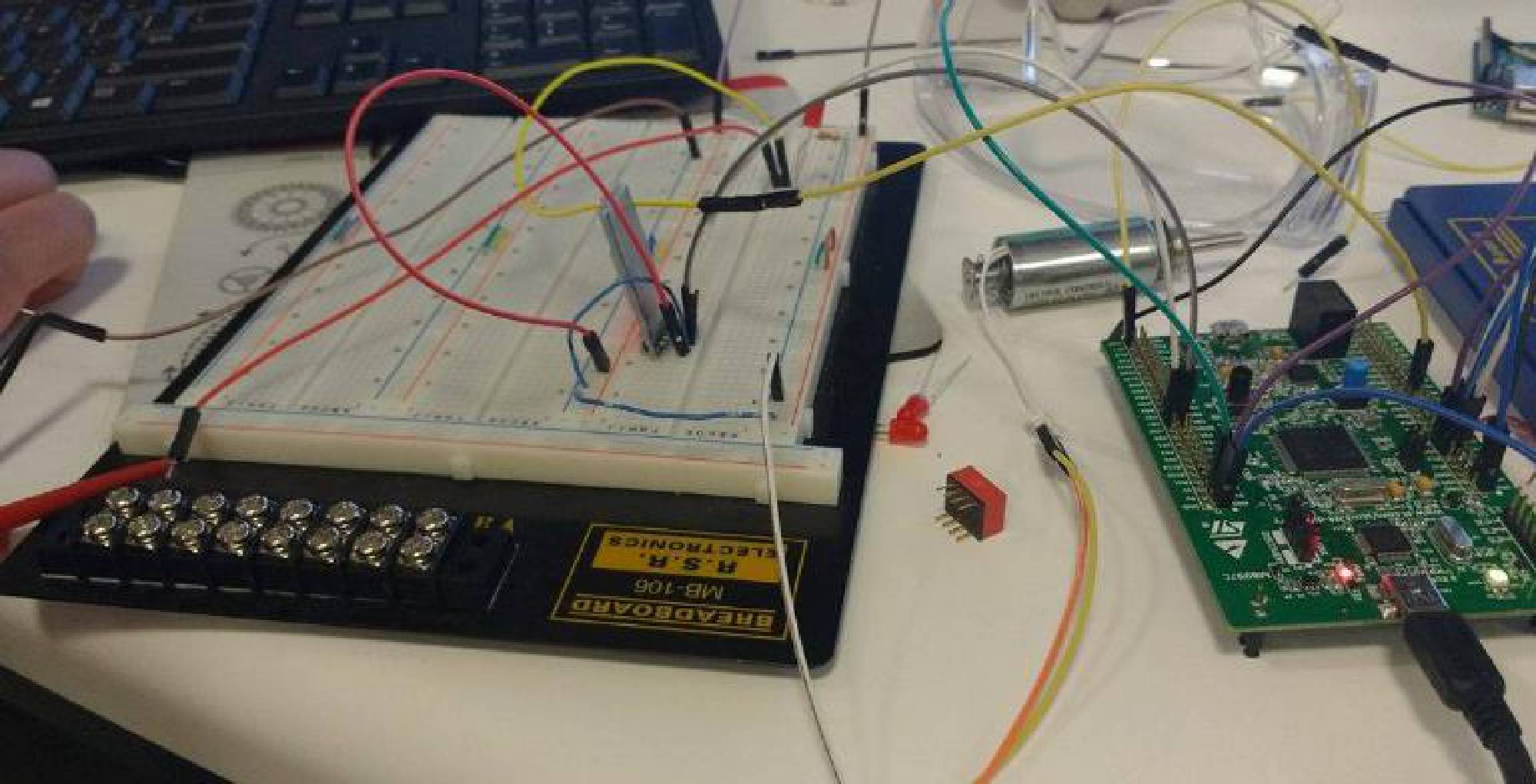
This week was about continuing to work on effectively pushing down on the frets. On Tuesday of this week, Kareem and I met up to test out a device he ordered called an EZ-fret which would be attached to the first few frets of the guitar and would be used to more easily push down on the frets. We tested it out with the solenoid directly pressing down the EZ-fret as well as with the solenoid lever pushing down on it. The EZ-fret definitely helped as when the solenoid pushed down, we were able to strum easily and play the appropriate notes however the solenoid tended to push down to hard and create a bit of a banging noise that played the string loudly. So we met up again on Friday and tried out a different kind of solenoid found in car door locks. This pushed down on it well and didn’t create the same noise, however we needed to find a way to pull it back up. Switching the polarities and applying the same positive 13 volts worked in pulling it back up, however we needed an h-bridge circuit to get this to work. I built one on a breadboard before realizing Joe had ordered a brand new h-bridge device and allowed me to use it. Unfortunately we couldn’t get it to work because we needed some sort of switch or a microcontroller to be able to switch the polarities with the push of a button, so that’s something that we’ll work on over the next few days. This week Sid was able to get the Bluetooth device to work and we decided on a microcontroller: the STM32-f4. In addition to all of this, I worked on the eagle tutorial and practiced a bit making new parts.
 H-Bridge
 H-Bridge 2
 WEEK 4 Pressing Test 1 CarDoor Lock
 WEEK 4 Pressing Test 2 CarDoor Lock
Total Hours: 6
This week, I mostly just worked on the Mechanical Overview. I talked with my teammates over designs we had come up with over the last few weeks and we decided on ones for the strumming and the fret pushing. We used my idea from a few weeks back where we use six solenoids that shoot out from the side and pluck the strings from there. We also went with the solenoid/lever system for pushing down on the frets with the help of Kareem’s ez-fret device that he ordered. I drew up the design in google sketchup. There was a bit of a learning curve to google sketchup and I had to get rid of a few designs but eventually, I got the hang of it. I also compared two similar products from YouTube and analyzed the packaging as well as work on the project packaging specifications. Wuxiucheng worked on the PCB footprint layout for the Mechanical Overview. I had a fairly busy week this week with other classes so I wasn’t able to accomplish as much as I wanted to this week, however I intend to catch up this weekend and next week.
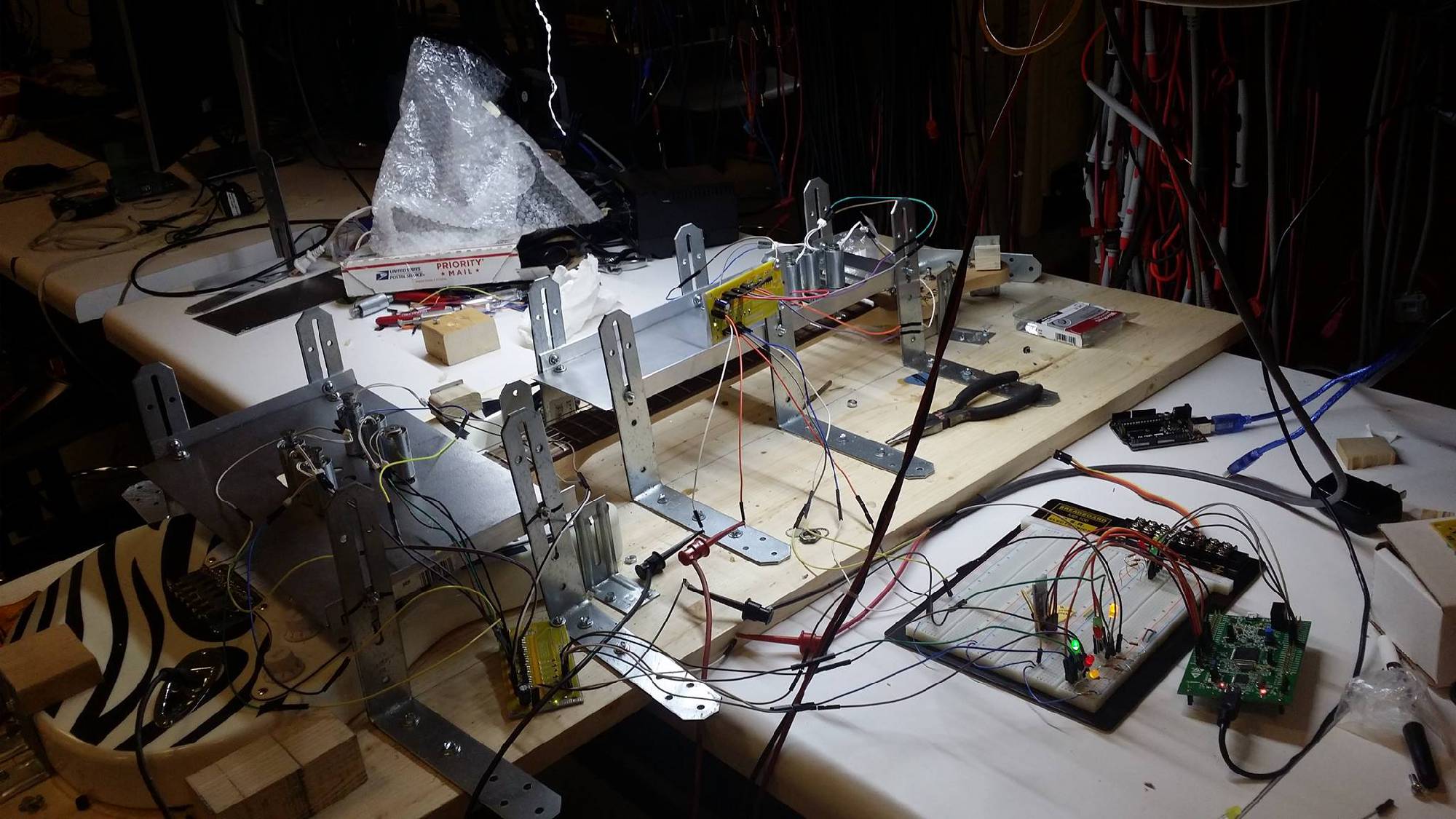
 Project Model
 Project Model
 Project Model
 Project Model
Total Hours: 7
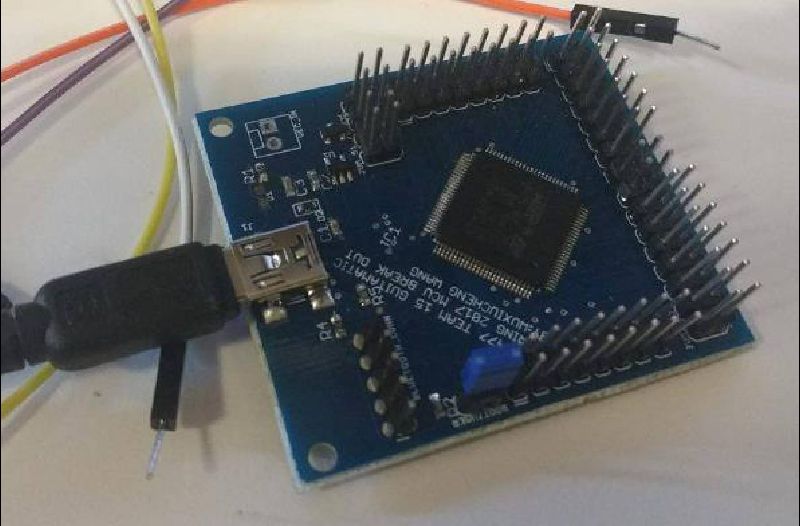
This week I tried working with our microcontroller, the STM32F4. I initially had trouble getting the computer to recognize the device however, after talking to Joe he gave me some lab documents that would help me interface with the device. From there I spent a few hours installing the proper drivers, Java, Eclipse, the system workbench, making changes to workspace preferences, and dealing with various error messages and getting a feel for Eclipse. I then read the second lab document regarding debugging with the stm32 however after dealing with different errors like “OpenOCD child process termination”, I was not able to get it to work. I think that part of the problem may be that we are using an f4 and the documents he gave me were for f0’s so later this weekend I may talk to Joe and try to snag an F0 and debug with that. I also worked on the rest of the eagle tutorial and continued practicing with creating different parts.
 Microcontroller Programming
Total Hours: 10
This week I worked with the STM32F4 Discovery microcontroller. After initially having trouble, I was finally able to get STLink properly installed. After this, I finished both tutorials Joe gave me which helped me get everything properly installed, appropriate preferences set up, as well as showing me how to debug a basic program. From there, I read some documentation on the microcontroller and other experiments Joe sent me which helped me understand what certain pins do and how they work, how to program with interrupts, etc. After following through a tutorial on youtube, I was able to get a blue led to light up [1]. This required understanding how to initialize a clock, a gpiopin and set bits. Once the main file was finished, I learned how to build the file, and flash it onto the microcontroller using STLink. Once I finished that, I decided to do something a little more complicated and get our servo to spin since we would likely need this for the strumming/pushing down a fret part of our project. I used code from another tutorial on youtube to make sure our servo would work, we won’t use that code in our final project [2] [3]. After downloading the file, building it, flashing it onto the microcontroller and making the appropriate connections, I was able to get the servo to spin.
Citations
[1] TizanaMenYo, "STM32F4 Tutorial: How to turn on LED on STM32F4-Discovery board using IAR IDE," in YouTube, YouTube, 2014. [Online]. Available: https://www.youtube.com/watch?v=Nvyncl8y7-Q. Accessed: Feb. 25, 2017.
[2] Tony Abboud, "STM32F4 Dev. | #5 - PWM servo," in YouTube, YouTube, 2015. [Online]. Available: https://www.youtube.com/watch?v=rllS99UwMNg. Accessed: Feb. 25, 2017.
[3] TDAbboud, "STM32F4_Examples/04_PWM_Servo at master · TDAbboud/STM32F4_Examples · GitHub," 2015. [Online]. Available: https://github.com/TDAbboud/STM32F4_Examples/tree/master/04_PWM_Servo. Accessed: Feb. 25, 2017.
 Microcontroller Testing 1
 Microcontroller and servo Test
 Programming
 Microcontroller and servo Test
Total Hours: 6
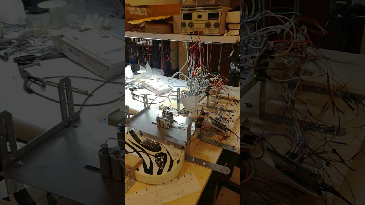
This week I helped our Kareem with the mechanical side. We started out by attaching a lever to the servo, and trying to press down on a fret with the lever. When we downloaded the servo program onto the microntroller and tried it out, it didn't work very well however we thought that this might be because of how much the servo was turning. We figured that we would need to modify the code to have it turn less and Kareem made the changes in the code, we put it back onto the microcontroller and tried it out. It worked a little bit better but not as well as we'd hoped. For most of this project we were thinking of using the EZ-fret device to make pressing down a fret more accurate, however we realized that that would require more force to push it down. When we were using one of our old solenoids we were using it on the acoustic guitar which required more force and on the EZ-fret which also required more force so Kareem and I decided to try it on the electrical guitar without the EZ-fret device. We adjusted the height of the solenoid to provide the ideal amount of force and it worked fairly well at holding down the fret. We tried this for all 4 corner cases (the high and low strings and the 1st fret and 8th fret) and it worked pretty well. There was a bit of a banging noise but since we'll be using an amplifier we hope that will mitigate the sound. We also took a servo with a guitar pick hot glued to it that Kareem and Alan came up with and tested plucking the guitar string with it and it worked fairly well. The 2 main points though to keep in mind are that the height has to be very precise for the plucking and we might possibly have a space issue. On our old packaging we had the plucking occur from the sides however due to space constraints and effectiveness, I think the plucking should occur from overhead. I spent some time researching other old projects and various resources online about how to best press down on the frets, however I think that our best bet at this point will be the solenoids and servos. Over spring break I'm hoping to critique our packaging in

Total Hours: 10
This week I continued working with the microcontroller. I spent time figuring out how to get an input working on the microcontroller with the GPIO. After reading various documentation and watching some youtube videos, I figured out what pins to use, how to configure them, and what input voltage signal to send to the microcontroller so it could be recognized as a logic 1. On a breadboard I added a push button to send an input signal into the microcontroller, and an led where the microcontroller would output a signal when the button was pressed. I wrote the microcontroller code on an infinite while loop such that while the input was 1, the output signal bit would be set so it would output 3 volts. This was meant to mimic what sending a note from bluetooth would be like for input and what sending a signal to the solenoid as output would be like. Once our group is completely finished with the support structure, we’ll test it out to make sure that we can send a note and push down on a string via the microcontroller. I also spent this week working on the homework.

 Microcontroller Testing
 Microcontroller Stamp Testing
Total Hours: 15
Continuing off last week, I set up a dip switch with 4 inputs and 4 led’s, where each dip switch input being toggled toggled the led’s from the microcontroller. In addition to that, I tried to create a voltage amplifier circuit with a 2n3904 transistor that would toggle the 3 volt output of the microcontroller between 0 and 24 volts. While it did create something similar to this, it didn’t work with the solenoid. I later had Kareem help me with this and we were able to get it to toggle properly, so when we toggled the dip switch, it toggled the solenoid. This would be similar to one of our PCB’s, which output the signals to the solenoids, which Alan tested and got to work. We also worked with sending pwm signals via the pwm module, however after various tests and debugging, we concluded that the device burned out so we ordered a new one. I also worked with Sid on sending data through the Bluetooth module via the microcontroller (instead of the Arduino) and on timing. I read some documentation for using the bootloader for our stamp module microcontroller. After Alan downloaded the DfuSe software and figured out how to get the stamp module recognized, I tried to figure out how to convert the software to the appropriate file type and load it onto the device. I discovered that I needed to download and use “dfu file manager” to convert a bin file to dfu so that It could be used via bootloader. While I was able to convert the file, and supposedly get it on the microcontroller, it wasn’t working. I debugged with the oscilloscope, changing the software to be more simple, uploading it to the discovery board, trying different pins to make sure our diagram wasn’t incorrect, etc. but still wasn’t able to figure it out. Hopefully this weekend I’ll be able to get the program properly running on the stamp module.
Hours: 12
This week was about trying to get the stamp module to work. Over the weekend I continued to try to load software onto the stamp module using the bootloader. I changed my code to be simpler, I changed the eclipse command to output hex files instead of bin and convert those to dfu files instead, I tried this method with the dev board and it working, however it still wasn’t working with the stamp so I tried to use jtag to upload it. I researched different videos and documentation to try and figure out how to get it to work but was having trouble at first. I found some documentation that explained which wires were needed and I connected those from stlink to the stamp to the computer, however the device wasn’t being recognized. I was able to get help with Joe on it however. He explained to me which pins were necessary for jtag and how to figure out which ones were which on the stlink ribbon cable. We tried loading it using the stlink device but it didn’t work. Then what we tried to do was load the code on using the dev board itself. We took off the stlink jumpers to disable part of the board. We had to update software and mess with different configurations in stlink to try and get it to work. When it wasn’t working, after looking at the schematic we realized that the reset didn’t have a pull up resistor so we soldered one on, then tested that pushing the reset would set the reset pin from 3.3v to 0v. When that didn’t work, I tried working with some of the other boards soldering the resistors onto there and testing with them to make sure one board wasn’t malfunctioning. While we were able to get the device recognized in stlink and according to stlink the program successfully downloaded, I wasn’t getting the behavior I was expecting. Kareem and Alan were however eventually able to get it to work, possibly because they used a different piece of code. While I tested to make sure that the code I was using worked on the dev board, I may have written it in such a way that it worked only with the dev board such as if I wasn’t using the right clock speed. In addition to all of this I worked with Kareem on testing the solenoids and pressing down on the frets.
 MCU Testing
 MCU Testing
Total Hours: 7
This week I worked with Kareem and Sid to test the circuit as a whole. We took the microcontroller and the code that Sid had worked on, connected it to the mosfet pcb, and connected those to the solenoids so that the microcontroller could play the notes. At first however, we noticed that the solenoids were not behaving as we expected. We combed through the code to make sure it was working properly, making minor changes to the timing, isolating certain parts, etc. as well as double checking the circuit and testing out individual solenoids, and using the multimeter to make sure they were receiving the proper signal. Eventually we discovered that the problem was that the power supply could only supply 1 amp and our 6 solenoids for plucking were eating up more than that. We tried a different power supply and it worked. I also helped reduce the noise in the solenoids by adding a piece of rubber inside some of them to dampen the sound, and I also helped Sid build a circuit for testing his code.
 Synchronization
Hours: 8
This week, we got the individual components working: the support system was done, we determined how we would strum strings such that rotation wouldn’t affect them, the MOSFET driver was working, the code was finished such that it could decode a MIDI file and send the appropriate outputs and when we uploaded this on a dev board and connected it through a breadboard it worked. We just needed to get it so that it would all work on the stamp board and not use a bread board so we could get preliminary PSSC’s. I worked with Kareem and Alan to try and figure out why the bluetooth module was able to work on the dev board but not the stamp board. We tried changing pins, changing the name of the device, use different phones to connect, etc. but couldn’t figure it out. While we will probably get back to making it work with bluetooth, our main priority was getting the preliminary PSSC’s and the bluetooth module wasn’t part of that so we tried to make changes to the code so that it would immediately start playing rather than wait for a signal to be sent via bluetooth to start playing. I started working with the code trying to change certain flags and debugging but then Sid sent some code from home that would work without the bluetooth module. Kareem and I uploaded it to the dev board, tried testing it with a multimeter and it didn’t work. After spends time debugging and changing things around, we decided to test it with an LED and it would rapidly blink which means it was just too fast for the multimeter to catch which meant it was working. When we tried uploading this to the stamp board and testing with an LED however, it didn’t work. What we’ve found so far is that we’ve been able to get basic programs to work on the stamp board but not more complicated ones like final one. This makes me think that there’s something in the code that’s written in such a way that it can work only with the dev board and not the stamp rather than there being a problem with the stamp itself, such as maybe an include file that can’t be put on the stamp board, or a file that might be placed in some external ram on the dev board but not on the stamp. This weekend, my plan is to work with everyone to rebuild the code one step at a time, try to upload it to the stamp and see where we first go wrong. In addition to all of this, I also worked on the educational report.
 BlueTerm App for testing Bluetooth Module
Total Hours: 12
Over the weekend, I spent a lot of hours trying a number of different things to get the code on the stamp, such as making very small changes in the code, changing the JTAG wires, changing how the bin file was made, making blinker programs and trying to load that, etc but eventually I was able to get it to work by using atollic. This was a big step as this was the last thing that no one could figure out how to make work and it was the only thing preventing us from getting our PSSC’s checked off. Then I worked with Sid and Kareem helping with incremental code changes and fixing the mechanical side to make sure that our project could properly play Happy Birthday. I then went in and got our final PSSC’s checked off. After that, I worked with them to get the project ready for spark challenge by adding heat shrink to the washers, gluing nuts onto the tips of the solenoids for fret pressing, helping with placement and spacing issues, wiring, etc. We would try to play the song and if it didn’t sound right, we would either re-adjust the solenoids or if it was a code issue, change the timing in the MIDI file. We then presented it at spark challenge and managed to get first place!
 Spark Challenge
 Spark Challenge
 Week 16 Demo 1
 Week 16 Demo 2
 Week 16 Demo 3